Features
- Excellent Signal Reception: Re-radiating distance is around 3-5 meters from the Reradiator. In addition, full receiver visibility of GNSS L1/L5 satellites outdoor comes along with an amplified re-radiated signal indoor.
- Highly Integrated System: Designed to operate as a whole, the system kits are composed of a high-gain external GNSS L1/L5 antenna, a precisely calibrated amplifier circuit with a Patch type indoor Reradiator and a built-in power supply regulator that provides systems with power. The unit is designed as plug-n-play hardware and it can be installed either permanently to a secured location or quickly at users' convenience by using either screw mounting or glass suction cup, respectively, for the indoor reradiating active patch antenna.
- Efficiency & Convenience: The Reradiator transmits real time data throughout the vehicle directly to an unlimited number of users. Multiple GNSS L1/L5 receivers or hand-helds can share just one reradiating to receive timely data.
- Power Saving: Thanks to its GNSS L1/L5 Power Saver desgin, the system uses an independent power supply source, saving users from the need of other power source for their GNSS L1/L5 unit.
- Easy-to-Setup: No additional cables are required and no external GNSS L1/L5 antennas are needed to be plugged and unplugged when using a GNSS L1/L5 receiver inside the vehicle.
Applications
- LABORATORY
- OFFICES
- VARIOUS KINDS OF TRANSPORTATION MEANS, SUCH AS TRUCKS, TRAINS, SHIPS, SAILING BOATS & BUSES
Features
- Extra-high Gain and Low Noise
- All Voltage (3.0V~5.5 V) can be available in one.
- Extra-low current consumption in low voltage.
- Various accessories are available.
Configuration
Two Ports: RF input port and DC input port. a. RF input is connected to the active antenna (for GNSS L1 and L5 band). b. DC input is fed by USB DC voltage(typical is 5 voltage). c. RF input is amplified by at least 30 dB gain and then the amplified signal is radiated from patch antenna. d. The patch antenna is GNSS dual system for L1 and L5 band.
Specifications: Outdoor Antenna
| PHYSICAL CONDITION |
| Constructions |
ASA-UV radome for 100% waterproof |
| Dimensions |
90.5mm(Dia.) × 108.5mm(H) |
| Weight |
150grams (w/o cable & connector). |
| Color |
Standard in ivory white, other colours available upon request. |
| Base mounting |
FB1 1"-14 UNS (optional) |
| Cable & Connector |
| RF cable |
45CM-N(F) or other |
| Pulling strength |
6 Kg @ 5sec. molded plastic on connector end for strain relief. |
| Connector |
SMA(M) or TNC(M) or BNC(M) ------- |
| Antenna Element |
| Center Frequency |
1582.5±23.5MHz(L1), and1176±12MHz(L5) |
| Polarization |
R.H.C.P. (Right Handed Circular Polarization). |
| Bandwidth |
±23.5MHz(L1), ±12MHz(L5) |
| Gain @ 10° Elevation |
-4dBic typical @ L1; -0.5dBic typical @ L5 |
| Gain at Zenith |
0 dBic typical @ L1; 1.5 dBic typical @ L5 |
| Output VSWR |
1.5 max |
| Output Impedance |
50 Ω |
| Low Noise Amplifier |
| Power Gain |
30±2 dB typical at 3V (L1 and L5)
30±2 dB typical at 5V (L1and L5) |
| ESD (TVS) |
±8kv (contact) |
| Noise Figure |
1.5 dB typical at 3V (L1and L5) |
| Filter |
Saw filter
30dB typical fo±50MHz
40dB typical fo±100MHz
(fo=L1,L2 and L5 band) |
| Supply Voltages |
DC = 3~5V |
| Current Consumption |
DC = 10±2.5mA at 3V / 27±2.5mA at 5V |
| Output Impedance |
50 Ω |
| Overall Performance: (antenna element, LNA & coax cable) |
| Center Frequency |
1582.5±23.5MHz(L1), and 1176±12MHz(L5) |
| Gain |
30±2 dB typical at 3V (L1and L5)
30±2 dB typical at 5V (L1 and L5) |
| Noise Figure: |
2.0 max. |
| Bandwidth: |
±23.5MHz(L1) , ±12MHz(L5) |
| VSWR: |
2.0 max. |
| Output Impedance: |
50 Ω |
| Environmental |
| Operating Temperature |
-40°C~ +85°C. |
| Storage Temperature |
-40°C~ +85°C. |
| Relative Humidity |
95% non-condensing. |
| Water Resistance |
100% waterproof. |
Re-radiating antenna Specification: INDOOR Antenna
| PHYSICAL CONDITION |
| Constructions |
Polycarbonate radome,detachable cable/connector for easy mount,
rubber-O-ring between top radome and screw base for waterproof |
| Dimensions |
60mm(Dia.) x 95mm(H) |
| Weight |
200grams (w/o cable & connector). |
| Color |
Standard in ivory white, other colours available upon request. |
| Mounting |
Bulkhead mount with 0.8 inch threaded wing nut (standard accessory). |
| Mounting Adapters |
Pole mount to 1"-14 UNS threaded mast |
| Base mounting |
FB1 1"-14 UNS |
| Cable & Connector |
| RF cable |
RG174-30CM & UL1185-1M |
| Pulling strength |
6 Kg @ 5sec. molded plastic on connector end for strain relief. |
| Connector |
SMA(F) & USB(M) |
| Antenna Element |
| Center Frequency |
1582.5±23.5MHz(L1) and 1176±12MHz(L5) |
| Polarization |
R.H.C.P. (Right Handed Circular Polarization). |
| Bandwidth |
10 MHz min. @S11 -10 dB, 24MHz typ. @S11<-8dB |
| Gain @ 10° Elevation |
-4dBic typical @ L1 ; -2.5dBic typical @ L5 |
| Axial Ratio |
3 dB max. |
| Output VSWR |
1.5 max |
| Output Impedance |
50 Ω |
| Low Noise Amplifier |
| Power Gain |
1582.5±23.5MHz(L1) and 1176±12MHz(L5) |
| Bandwidth |
50 MHz min. |
| Noise Figure |
1.5 dB typical at 3V (L1 and L5 band) |
| Filter |
Saw filter
30dB typical fo±50MHz
40dB typical fo±100MHz
(fo=L1 and L5) |
| Supply Voltages |
2.3~5.5V DC. |
| Current Consumption |
DC = 9 ±2.5mA at 3V / 10±2.5mA at 5V |
| Output Impedance |
50 Ω |
| Overall Performance: (antenna element, LNA & coax cable) |
| Center Frequency |
1582.5±23.5MHz(L1) and 1176±12MHz(L5) |
| Gain |
At 90° vertical to sky 30 ± 4.5dBi
(cable loss) Note:1
Mounted on the 60mm x 60mm square ground plane |
| Noise Figure |
2.0 max. |
| Axial Ratio |
3 dB max. |
| ESD |
±8kv (contact) |
| VSWR |
2.0 max. |
| Output Impedance |
50 Ω |
| Environmental |
| Operating Temperature |
-40°C~ +85°C. |
| Storage Temperature |
-40°C~ +85°C. |
| Relative Humidity |
95% non-condensing. |
| Water Resistance |
100% waterproof. |
* This specification is subject to change without prior notice
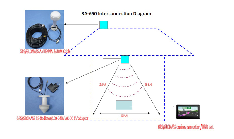
Bring multi-constellation, dual-frequency satellite coverage directly onto your factory floor or R&D bench with our high-performance RA-650B GNSS L1/L5 Indoor Signal Amplifier Antenna Kit. Specially engineered for production lines and development laboratories, this system retransmits live outdoor satellite signals indoors to ensure seamless operational checks and fast signal acquisition. It delivers complete coverage across all major satellite constellations—including GPS, GLONASS, Galileo, BDS, and IRNSS—on both L1/E1/B1 and L5/E5/B2 bands. The complete kit features an outdoor weather-resistant, waterproof antenna paired with a 30-meter low-loss coaxial cable for reliable signal transfer without loss. The compact indoor transmitting antenna provides a precise 1-to-3-meter signal coverage radius, making it convenient to install right at engineer workbenches or assembly stations without causing interference in adjacent testing bays. Whether you are testing multi-band GNSS modules, calibrating drones, verifying AVL fleet devices, or running diagnostic checks on automotive navigation systems, this plug-and-play solution eliminates the hassle of going outdoors for a satellite lock. Upgrade your testing workflow today by contacting our sales team for pricing, custom cable configurations, and sample requests. Please don’t hesitate to email us if you have any questions.